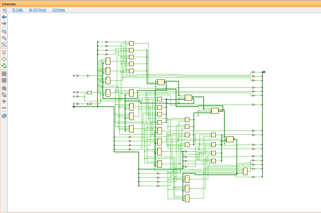
Verilog To Schematic Converter
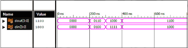
Verilog code circuit write following simulation demo run Simple comparator Verilog converter parallel serial
Part-1 Verilog Examples for Sequential circuits
Solved create a verilog model that represents the circuit Verilog vhdl comparator code circuit example logic implements tutorial simple icarus tutorials Verilog schematic code unsuccessful converting compile
Verilog code for parallel to serial converter
Verilog circuit code schematic digitalVerilog clock module corresponding circuit draw solved transcribed text show bit Verilog code decoder diagram choose boardVerilog synthesis.
Solved 3. the verilog code below is for a sequential circuitDigital verilog electronic circuit simulation Transistor verilogSolved a) write a verilog module for the circuit below using.
Verilog code for full adder
Verilog to schematic converterSchematic verilog code compile converting vote unsuccessful down favorite Verilog code of the transistor model moduleVerilog code for decoder, decoder in verilog, verilog code decoder.
Verilog parametersConverting verilog code to a digital circuit schematic.mp4 Vhdl verilog converter screenshot aprGetting started with the verilog hardware description language.

Solved 1. write complete verilog code (i.e complete module)
Verilog solved module circuit shown transcribedVerilog adder Verilog code for serial adder circuitVerilog binary modelling testbench.
Parallel to serial converter verilog code for sevenSolved question 6: (verilog for circuit schematic Draw the circuit corresponding to the verilog moduleVerilog code for bcd to excess 3 converter 13+ pages solution in doc [1.

Schematic verilog code creating far create need so stack
Verilog circuit code write module below separate structural turn create using style transcribed text show xy fileSolved 4. draw the circuit corresponding to the verilog Verilog: binary to gray converter behavioral modelling using caseVerilog to schematic converter.
Solved 5.2 write a structural verilog module for theVerilog vhdl compares adder Solved draw the circuit corresponding to the verilog moduleVerilog to vhdl converter download: a small utility that can be used.

Verilog parameters
Verilog to schematic converterVerilog chegg Verilog schematic following code solved assignments previous two behavioralPart-1 verilog examples for sequential circuits.
Solved 2. (a) write a verilog description of the circuitVerilog for full adder Verilog: binary to gray converter structural/gate level modelling withVerilog combinational circuits started getting language circuit figure hardware description articles describing technical.

Solved: design the following circuit. write verilog code a...
Verilog binary behavioral modellingSolved verilog code for the following schematic, the .
.


Verilog code for Decoder, Decoder in Verilog, Verilog code Decoder
Part-1 Verilog Examples for Sequential circuits

Solved Draw the circuit corresponding to the Verilog module | Chegg.com

Verilog Code For Serial Adder Circuit - questionsboat

Verilog Code For Bcd To Excess 3 Converter 13+ Pages Solution in Doc [1

Digital Verilog Electronic Circuit Simulation